my idea for the project is to build a formula 1 racing car
which could move by itself and avoid any obstacles in its way or to be controlled remotely by bluetooth.
https://www.youtube.com/watch?v=_xEvb2hIh_I
https://www.youtube.com/watch?v=esnqgaKJTCs
-----------------------------------------

We decided to build a F1 type race car with Lego EV3 parts, because we are both fans of the Formula 1 races.
Photo: Mercedes on the left for the German GP 2019 and our EV3 on the right
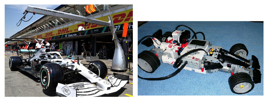
Our car uses three motors. Two Large Motors in the rear make the car drive, while the Medium Motor in the front lets you steer the front wheels. Think of the rear motors as the car’s engine and the motor in the front as the car’s steering wheel.
Building instructions:
F1 CAR BuildingInstructions.pdf
More photos of our design are shown below in our group Story.
Here is a video of our F1 car in simple line following.
Programming
After building, we had to program its driving. For the prototype car, the new Lego programming environment named EV3 Classroom was used. This new software is Scratch based block programming, so it was easier for the students to get their hands on since they were already familiar with Scratch programming. This was important because after our Erasmus+ project was extended due to Covid, the initial group of students has graduated from School and a new group of students joined in the year 2020-2021. These new students were not familiar with Java programming yet, so the leJOS porting of the code was left for later.
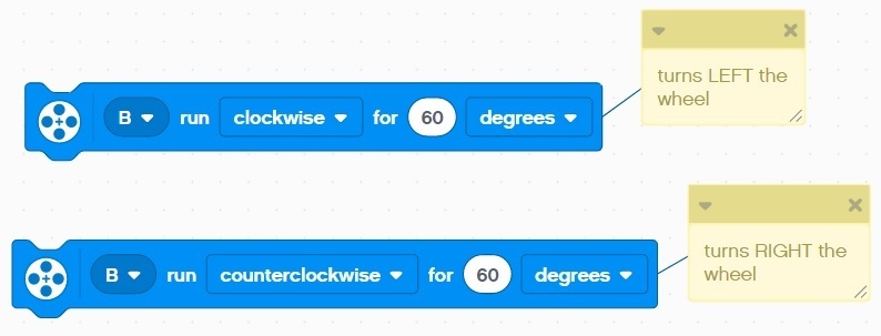
Steering Left / Right
For steering, the EV3 medium motor (on port B) on the front, can rotate clockwise or anticlockwise to steer the wheel LEFT or RIGHT respectively.
When the wheels are positioned directly in the center, for driving straight, it is assumed a zero degrees motor position by resetting the motor tacho degrees.
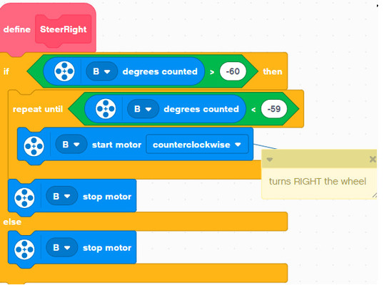
In order to avoid over-steering and stalling the motor or breaking the gear mechanism, we can make the above blocks safer by applying some over-steering degrees checks as follows.

Return Steering to Center position automatically
So after fully steering left or right the wheels it is a good practice to return the steering to the center position (zero degrees) automatically. This will ease our programming code and also allows for some jitter compensation on the centering (through some degrees boundaries on the code checks) of the mechanism. In addition it returns the wheel in a known center position so that it is ready for it to apply the next steering Left or Right command. The following code performs this automatic positioning of the wheel at the center (straight ahead). Notice how the near zero wheel position is achieved (boundaries -20 to 20 degrees) since the steering system will never be exactly at the zero degrees.

Initialising Steering at the Center position at Start
Finally, another problem is that initially when starting the execution of the program, the position of the car’s steering wheel is not known and it can be at any random degrees (from the point the program stopped at its previous run).
So to tackle this the steering wheel can be forced to any fully left or right position and then centered with accuracy by providing the exact degrees (these are pre-discovered by trial & error). The following code does this.
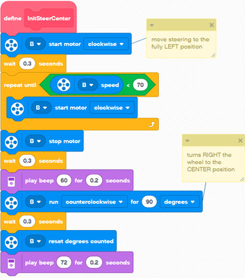
In this code there is a repeat until loop that moves the steering to the fully left position. Since we set the motor drive speed to 80% the end position is discovered when this speed is dropped below say 70%.
Then with trial & error we found that a counterclockwise motor run of 90 degrees will bring the steering just to the center position.
Simple Line Following
We decided to make our F1 car autonomous in a way that it can follow a black predetermined line on the floor. This task is called line following. In its simplest way we utilized a single EV3 Colour sensor in reflected light mode operation. Basically the sensor shines a bright light and measures the reflected light intensity from that surface. Darker surfaces absorb more light so our car can distinguish between lighter and darker areas.
For example

This is the so called light sensor calibration. The above calculations can be made manually or performed inside the programming code with the use of variables. After it can also be normalized in the range 0 to 100.
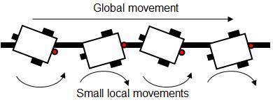
The vehicle then can then be made to follow either the left or right edge of the black line. It effectively bounces on the edge of the line.

This is the code operation

You can see how this long vehicle F1 car performs in the video on top of this page.
Here is our EV3 Education Classroom code for it: F1 Car code