Introduction
A two-wheeled self-balanced robot was decided to be investigated in order to appreciate the speed of code execution supported by leJOS (Java) under LEGO EV3. We wanted to test the Gyroscope sensor under leJOS and how this can be used to allow a robot to make its own decisions without operator invention.
This balancing robot uses motion equations based on existing documentation (Christensen, B. K. (2017), GyroBoy – a self-balancing robot programmed in JAVA with leJOS EV3, Technical University of Denmark).
Previously there have also been some Segway Robots implemented with the older LEGO Mindstorms NXT brick. Sensors used in the past were measuring the distance from ground but overall the gyro sensor was found to be a more capable sensor to keep the robot balanced and it provided an improved method for measuring the robot’s rotational angle.
LEGO EV3 also provides a ready building model with instructions named GyroBoy as depicted in the following cover (left side).

EV3 GyroBoy building instructions by LEGO link:
https://education.lego.com/en-us/product-resources/mindstorms-ev3/downloads/building-instructions
LEGO also provides the programming code of the GyroBoy in its proprietary block programming language. Here is a description:
https://education.lego.com/v3/assets/blt293eea581807678a/blt6442d49d724f3570/5f8803d01c5db60f7d0ae38e/ev3-program-description-gyroboy.pdf
Our Design
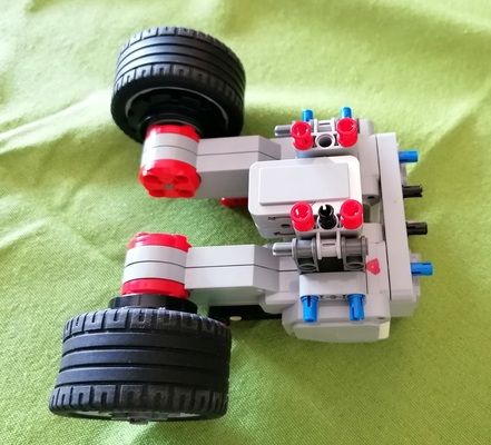
With Gyroboy as a starting model our students built their own custom-made much simpler and more robust balancing robot. It only utilizes a Gyro sensor and 2 large motors. Here are some photos of it:


VIDEO
Here is a video from its testing. It balances alright!
Control Mechanism
The act of balancing the robot is very similar to that of balancing a Segway. It uses a feedback control loop that continuously computes motor power based on the robots position and how much it tilts.
To balance the robot we need readings from the gyro sensor and from the motors.
From the gyro sensor we get the angle velocity (angular velocity of the sensor that is measured in Degrees per second) named (phi dot). This indicates how fast our robot falls. In the leJOS class EV3GyroSensor the mode getRateMode() is used. A positive angle velocity means that the robot is falling forward, and a negative angle velocity means that the robot is falling backwards.
Then we Integrate this velocity in the JAVA code to get the gyro angle that is how much the robot tilts forward or backwards, named φ. An angle value of zero means that the robot is perfect upright. A positive angle means that the robot is tilting forwards, and a negative angle means it is tilting backwards.
Inputs and outputs of the balance controller

The 2 EV3 wheel motors will be set to be controlled as unregulated motors so just the controller sets in the fastest possible direct way the appropriate power to the motors to correct the balancing. We don’t set them as regulated since we are not going to instruct them to rotate by a specific angle.
From the motor we can read how much the wheels have rotated since the start of the program. This is called the tacho-count and is measured in degrees. It is shown as the angle θ (theta) in the Figure. A positive angle means that the robot has moved forward from its starting position. The control program will try to drive the robot back to its original position while at the same time keeping the balance. A negative angle, as shown in the figure, means that the robot has backed up from its starting position, and the control program will try to drive it forward again. The leJOS UnregulatedMotor provides us the method getTachoCount that returns the tachometer count of the motor in degrees, that is the information we want to pass in the controller. Additionally in the JAVA code the motor rotational speed (denoted as theta dot) is computed by first taking a running average with length 4 measurements and then take the derivative with respect to time. The time step in the loop is set to Δt=10ms.
Balancing the robot is carried out in a so called feedback control loop shown in Figure.

In the control loop the so called error signals, the gyro angle velocity (phi dot) and the motor rotation angle θ (theta), (also referred to as the motors tacho-count ) are feed back into the equation that computes the new power for the motors – also known as the control signal.
The control constants are taken from the earlier mentioned LEGO proprietary block program as it is very difficult to find out the optimal parameters by scratch.

The values for the Control constants are: k1=15 , k2=0.8 , k3=0.12 and k4=0.08
thus the gyro angle is by far the most important parameter (k1).
Moving the robot around
External control signals can be given to set the robots forward speed, and to steer the robot.
By adding a displacement value s to the motor rotational angle in every iteration of the control loop, the robot can be driven forward or backward. Notice, that the control loop, in addition to keeping the robot upright, also will make the robot balance on its initial position. By adding a negative value of s, the control loop is tricked to believe that the robots position is behind the starting position, and hence will drive it forward. A positive value of s will drive the robot backward. This is denoted with the variable named speed (value s) in setSpeed(double s) of the JAVA code.
Steering the robot left or right is done by adding a value t (in the Figure) to the left motor power, together with the same negative value –t to the right motor power. A positive value of t will turn the robot right, while a negative value will make it turn left. This is denoted with the variable named direction (value d) in turn(double d) of the JAVA code.
JAVA code here:
GyroBoy.java