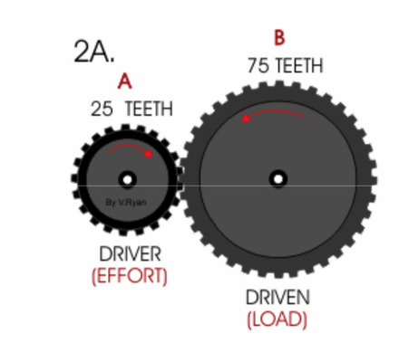
Gear ratio Z=No of teeth on driven gear/No of teeth on driver gear
According to figure
Z=75/25= 3/1
so gear ratio is 3:1
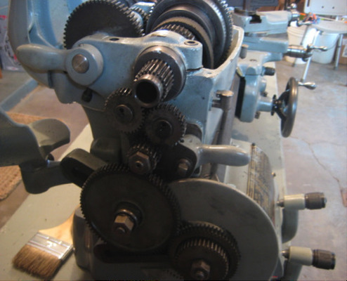
What you see here is the complex gear train that allows you to change the spindle speed, so that the chuck of the lathe rotates at the proper speed.
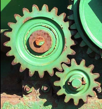
The picture above shows a simple gear train made up of a couple of spur gears. These are the common gears (or cogs) that look like a wheel with teeth around the rim.
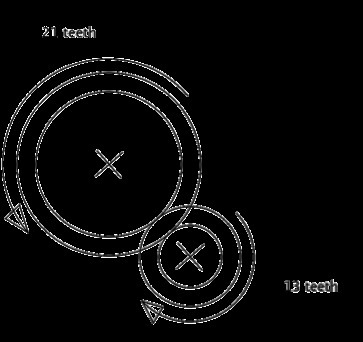
Next to it is a diagram showing how you would draw this gear train.
Gears consist of toothed wheel fixed to shafts. The teeth interlock with each other, they are also called spur gears because they mesh together. Let’s call the larger one DRIVER, as it is turned by a motor. As this gear turns it meshes with a smaller gear which begins to turn as well, in this case the smaller gear is called DRIVEN gear.
The speed of the driver gear is called INPUT SPEED, the speed of the driven gear is called OUTPUT SPEED.
which one rotates faster, the smaller or the larger?
Given the definition of gear ratio and the output speed formula:
The difference between these two speeds is called the velocity ratio, or the gear ratio, and can be calculated using the number of teeth. The formula is:
Gear ratio = number or teeth on driven gear ÷ number of teeth on the driver gear
If you know the gear ratio, and the speed input at the driver gear, you can calculate the speed output at the driven gear using the formula:
Output speed = input speed ÷ gear ratio